


Moles, to the general population, show their presence from time to time by turning landscaped areas of vegetation into a ski mogul course. Anyone who has had this happen to them knows the head-dropping chore it is to reshape these landscaping areas. There are benefits from a mole creating underground tunnels; it mixes soil nutrients, aerates the soil, and promotes additional drainage, but we’re not going down that path.
Today. the focus is on one of the many processes to install underground pipelines (sewer, water, gas, etc.) by trenchless technology methods. Common trenchless technologies used in the industry today include microtunneling, tunnel boring machine (TBM) aka “mole” (contractor’s lingo), pipe ramming, auger and bore, hand mining, and horizontal directional drilling.
The District’s Pumping Station 17 Force Main Relief Phase 2 Project, used in the project example described in this article, is a pilot tube microtunnel.
Why and when trenchless is used
Open-cut technology is the preferred method for the installation of underground pipelines. It is used to maximize daily production rates and keep costs to a minimum. But unfortunately, projects occasionally require the need to cross a constraint that does not allow for the construction of an underground pipeline by conventional open-cut methods.
These constraints are usually a waterway crossing such as the Yahara River, a major transportation corridor such as the Beltline, and railroad corridors. These transportation and recreational corridors are necessary for the economies and well-being of all that depend on them; therefore, minimizing or eliminating any impact from a closure or detour of traffic is sometimes required. This is when we must cross using trenchless technology.
How trenchless works
Let’s break this down…visualize you have a piece of wood, drill, hammer and nail. Trenchless technology takes these basic tools to drill a hole through the soil (wood) and push (hammer) the pipe (nail) through the soil (wood). Now instead of your 1/8-inch diameter drill bit and 5d penny nail upsize that to a 42-inch diameter drill bit that is going to lead the way for a 42-inch diameter sewer pipe to be pushed by a jacking frame (includes the frame skid, operational controls, hydraulic connections, and hydraulic cylinders) with a thrust force of 265 tons using a hydraulic pump and a lubrication system. There are jacking frames that range in thrust force from 100 to 1,200 tons depending on the application.
There are many methods to install a pipe by trenchless technologies, as listed above, but writing a narrative on that would put most people to sleep by page two, if not already. District projects using trenchless, past and present Within the District’s collection system, we encounter the need to install a pipe by trenchless technology from time to time under a capital improvement project. The selected technology widely varies from project to project based upon multiple conditions including, but not limited to, soil conditions, the presence of rock/cobbles, groundwater levels, access, size and length of pipe, and work zone area.
District engineers have used trenchless technologies in 34 projects, spanning the years from 2000 to today. Project engineers Jeff Klawes, Eric Hjellen and Theran Jacobson compiled a full list of these trenchless crossings and the technologies used. Below are a few of the most recent, longest and largest in diameter.
| Project | Size | Trenchless Technology Method | Year | Trenchless Installation Crossing |
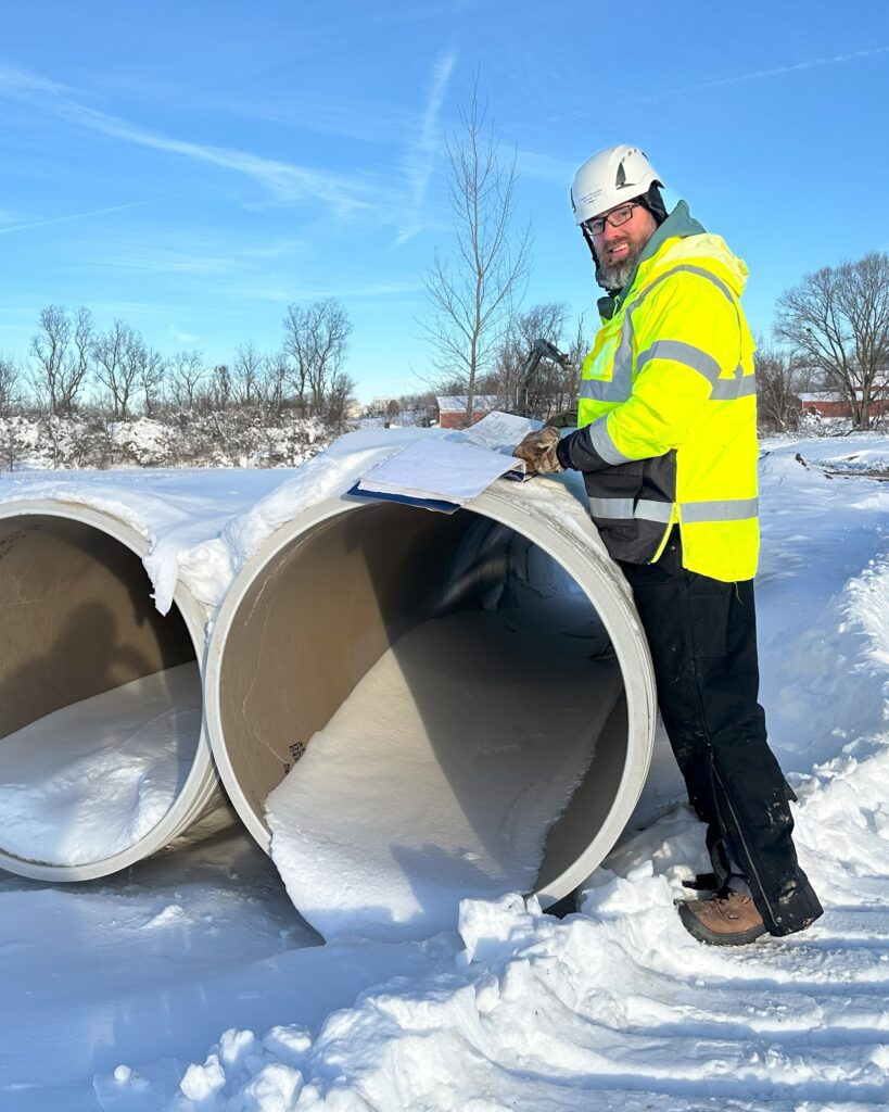
| PS 17 Force Main Relief – Phase 2 | 42″ diameter sewer; 105′ length | Pilot tube microtunnel | 2024 | Military Ridge State Trail (railroad corridor) |
| PS 17 Force Main Relief – Phase 1 | 72″ diameter casing; 160′ length | Pipe ramming with auger bore | 2021 | CTH M / South Main Street |
| West Interceptor Shorewood Relief – Phase 2 | 48″ diameter casing; 45′ length | Jack and bore | 2022 | Railroad tracks |
| Northeast Interceptor – Truax Relief | 60″ diameter casing; 160′ length | Pilot tube auger bore with pipe ramming | 2019 | US 151 / East Washington Avenue |
| Northeast Interceptor – PS 10 to Lien Road Relief/Replacement | 87″ diameter casing; 130′ length | Tunnel boring machine | 2010 | Sycamore Avenue |
| West Interceptor Campus Relief – Phase 2 | 48″ diameter; 600′ length | Microtunnel | 2000 | Campus Drive |
Trenchless project example – Pumping Station 17 Force Main Relief Phase 2
Currently, the Pumping Station 17 Force Main Relief Phase 2 Project is under construction with three segments of pipeline being installed by trenchless technology. One of the segments was completed on January 25, 2024, and crossed under the Military Ridge State Trail in the Town of Verona, just west of Pumping Station 12.
The technology chosen was a pilot tube microtunnel. Microtunneling is an advanced form of trenchless technology that allows the operator to steer the boring machine remotely from outside of the tunnel. This is unlike a conventional tunnel boring machine (TBM) where the operator is in the tunnel.
How the pilot tube microtunnel works
The pilot tube microtunnel incorporates the technology of three other trenchless technologies: pilot tube head (steering), which is similar to horizontal directional drilling; remotely operated guide system of a microtunnel; and soil removal from a conventional auger bore.
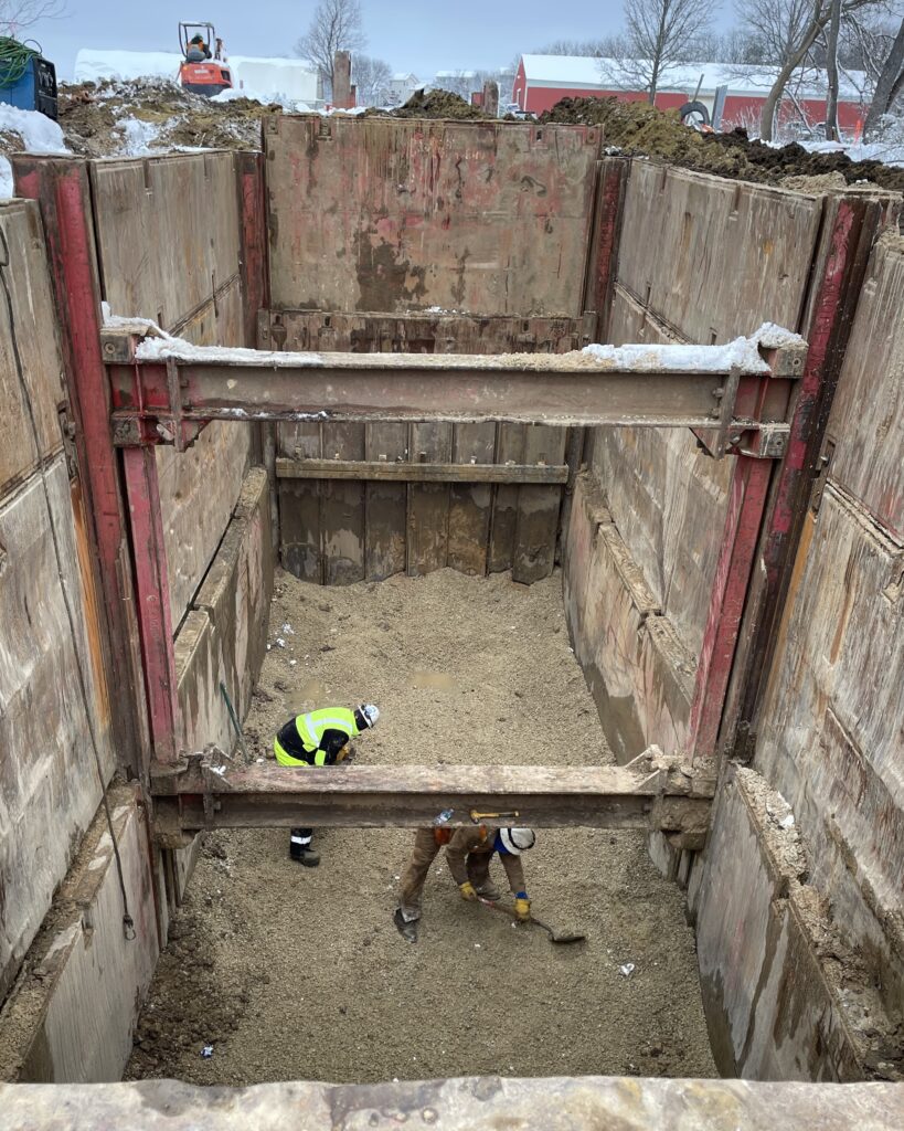
The incorporation of this technology grouping creates three major steps for the pilot tube microtunnel. There are of course minor steps to get to the major steps listed below. The minor steps are all necessary and, depending on the length of tunnel, the setup duration to install the pit and trenchless equipment is much longer than the duration to install the pipe by the selected trenchless technology.
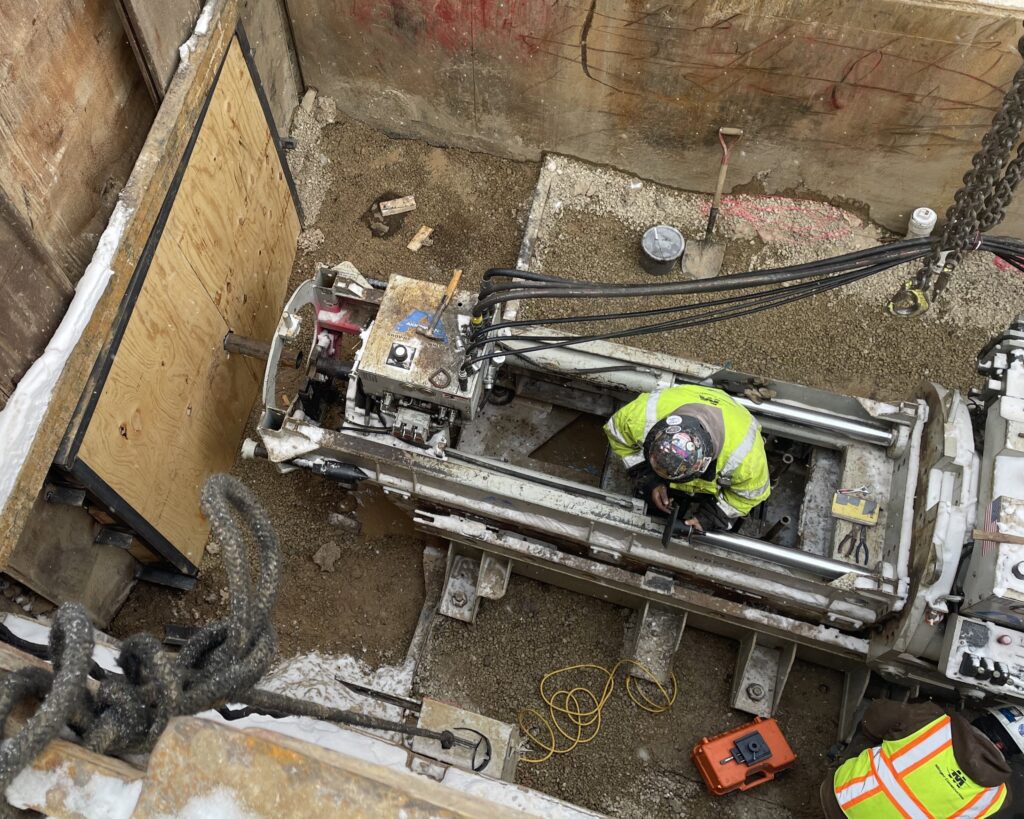
Some of the minor steps include erosion control installation; excavating and installing slide shoring systems for the launch pit and receiving pit; installing a dewatering system; constructing a foundation for each pit, either gravel or concrete; and finally, installing the jacking frame and microtunneling guided boring equipment – theodolite, LED target, operator control center, etc.
Here are the three major steps for the pilot tube microtunnel:
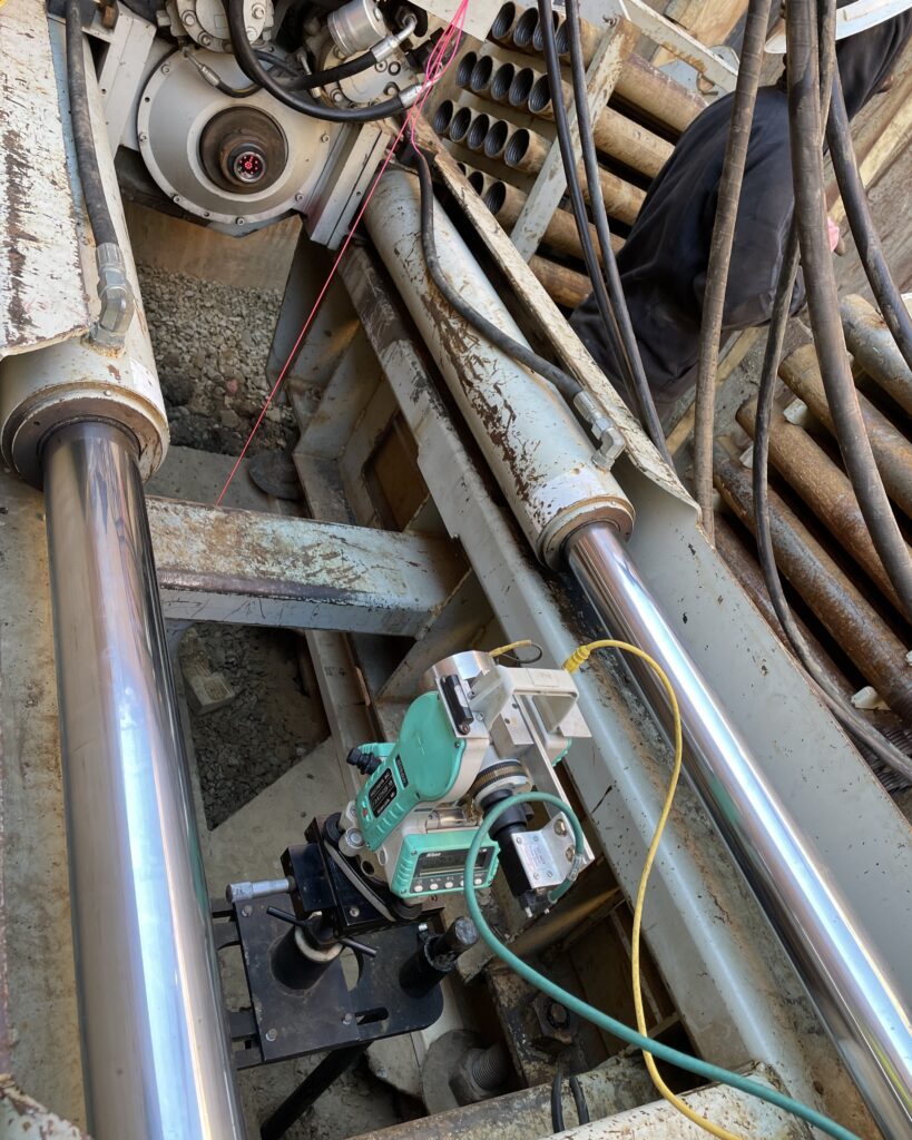
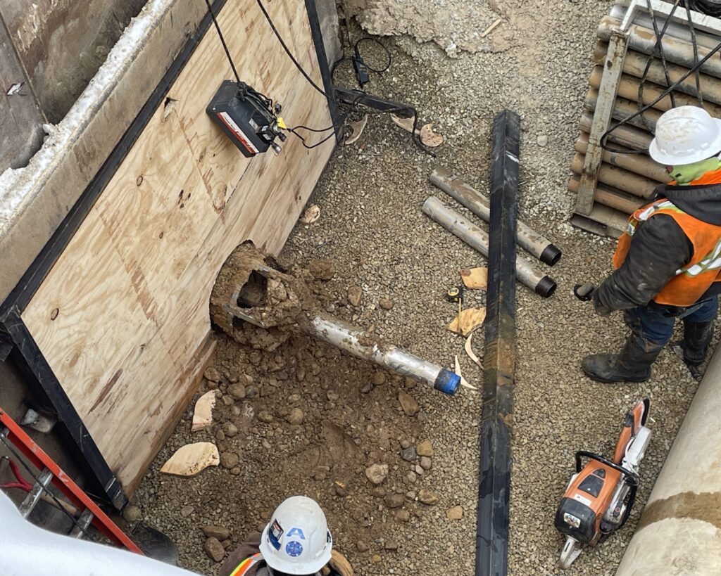
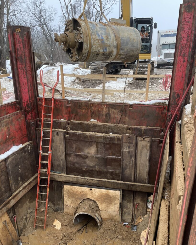
Step 1: Setting the alignment: Four-inch pilot tubes are pushed from the launch pit to the receiving pit over the length of the tunnel in order to set the horizontal and vertical alignment of the tunnel. A theodolite (camera) is installed in the launch pit and tracks the LED target as the pilot tubes advance. The pilot tubes are pushed through the door of the receiving pit to complete this step.
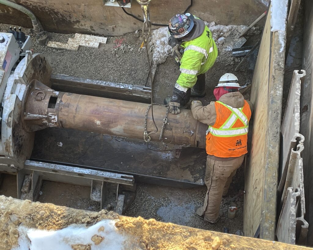
Step 2: Upsizing the tunnel: Next a reamer head dart is connected to the last pilot tube to aid in upsizing the tunnel. The reamer head is then followed by a 16-inch steel auger casing pipe.
As the 16-inch steel auger casing pipe is advanced, the auger is rotating and soil is removed (referred to as spoils) and deposited in the launch pit into a steel tub. Once the steel tub is full, the spoils are deposited outside of the launch pit by an excavator – this occurs multiple times. As the casing pipe is advanced, the pilot tubes are removed in the receiving pit. Once the reamer head is through the door of the receiving pit, this step is completed.
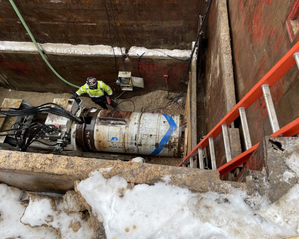
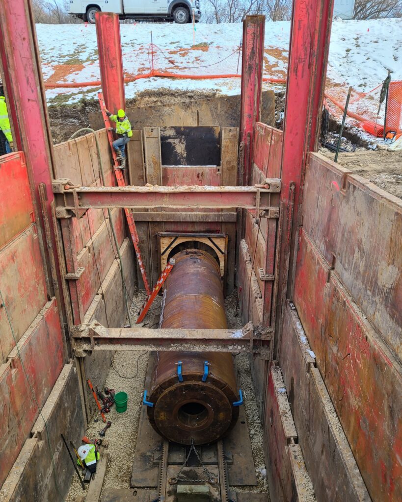
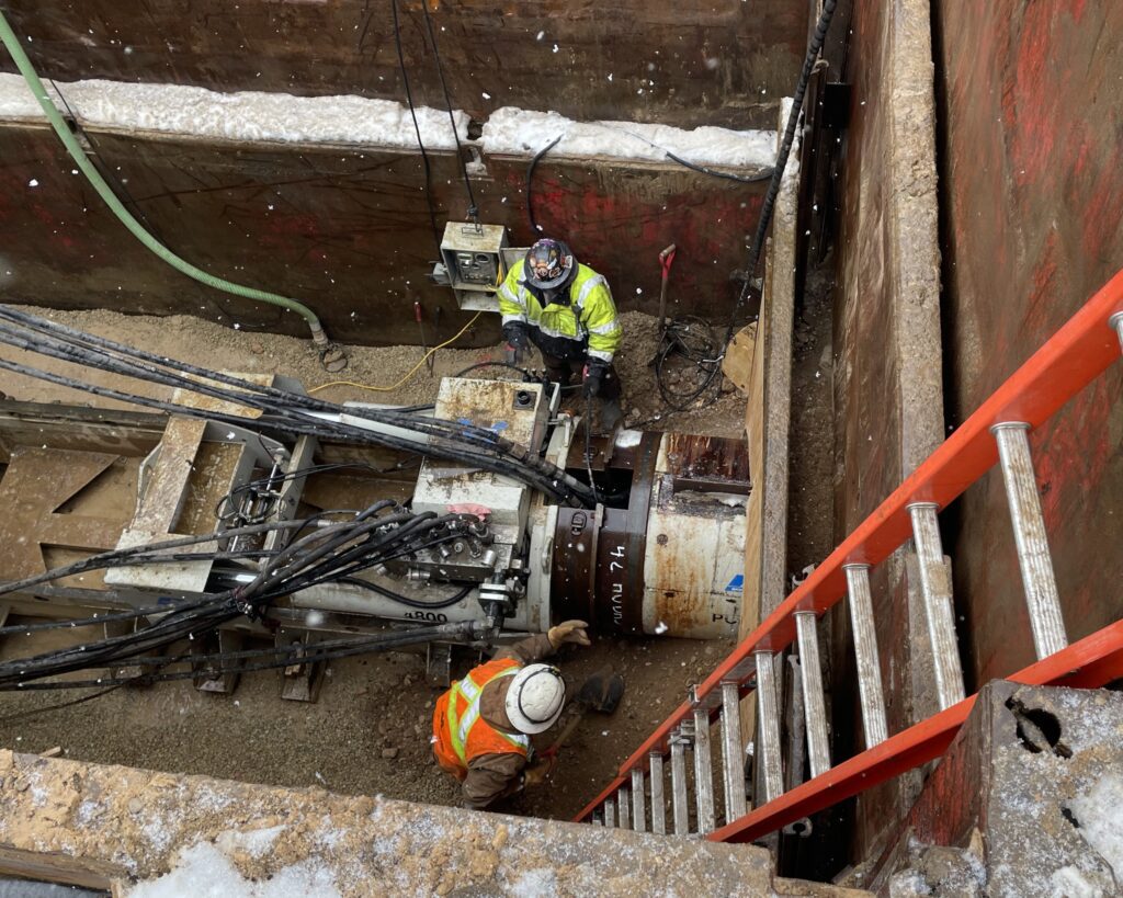
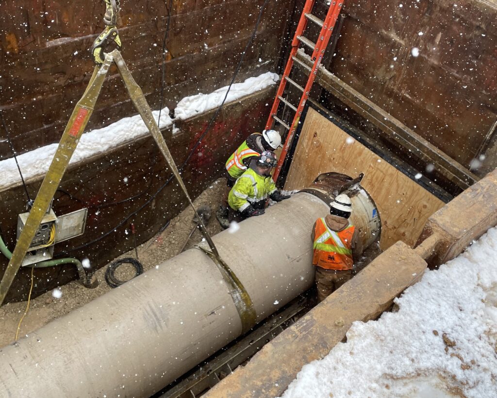
Step 3: Cutting in the permanent pipe: The final step is to place the microtunnel power cutting head into the launch pit.
The head is connected to the last 16-inch steel auger casing pipe and partially advanced into the tunnel. Then the 42-inch diameter Hobas jacking pipe is placed in the frame skid. The pipe is partially inserted into the tail of the microtunnel power cutting head and in a push ring at the head of the jacking frame. The pipe is now ready for advancement into the tunnel.
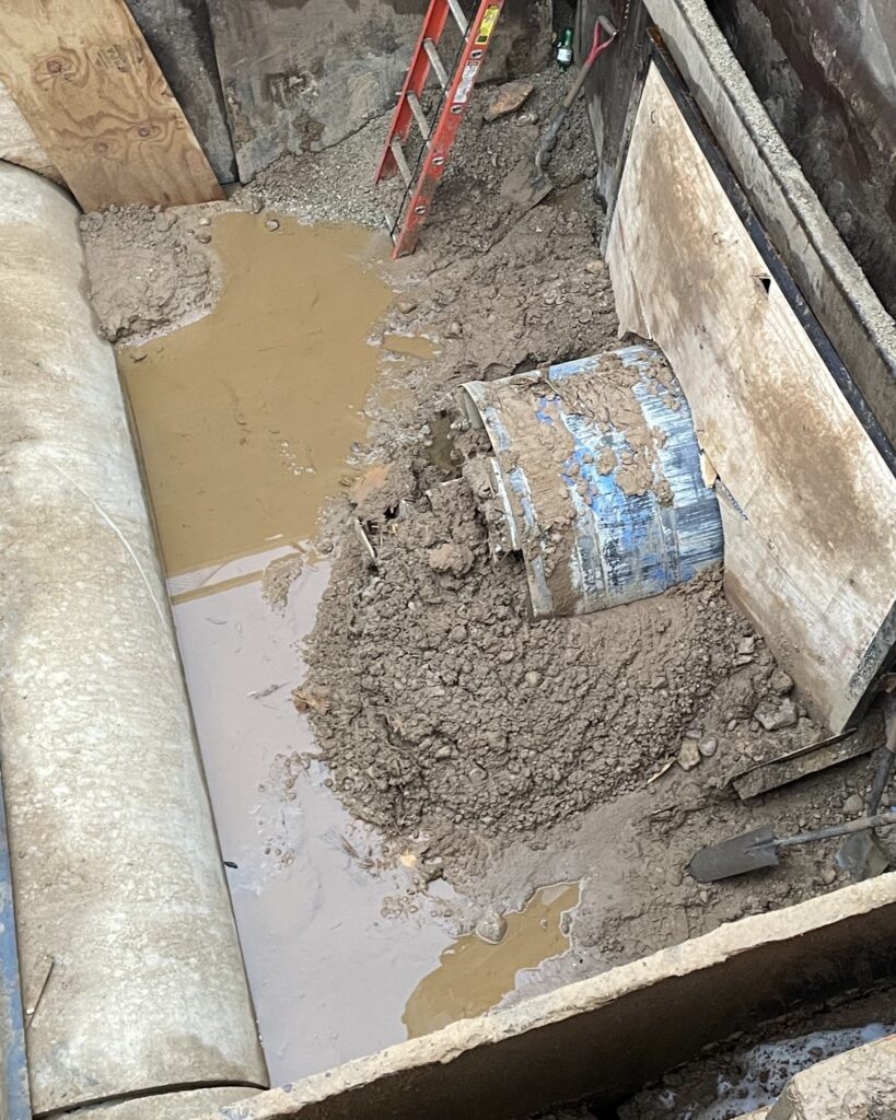
As the microtunnel power cutting head advances, three processes occur: the face rotates, cutting the soil; the rotation of the augers in the 16-inch steel casing pipe are reversed so the spoils generated are deposited into the receiving pit; and the jacking frame pushes the pipe.
The 16-inch steel auger casing pipes are removed section by section as they are advanced into the receiving pit, just as the pilot tubes were removed in step 2. Once the microtunnel power cutting head is through the door of the receiving pit, it is removed and the pipe is advanced through the receiving pit door, completing this step.

Why this project needed microtunneling
Pilot tube microtunneling was chosen for the Pumping Station 17 Force Main Relief Phase 2 Project for a variety of reasons, the most crucial of these being the soil conditions, small work zone and reuse of the same tunneling equipment for all three crossings.
Learn more about the project in the blog article “Project spotlight: Pumping Station 17 Force Main Relief, Phase 2” or read more about the project, find updates, documents and more on the project page.
By Theran Jacobson
