


The Flow Splitter Improvements project is a big one happening at the Nine Springs Wastewater Treatment Plant this year. What this crucial piece of infrastructure does and how it functions might be of interest to inquiring minds.
Flow splitter function
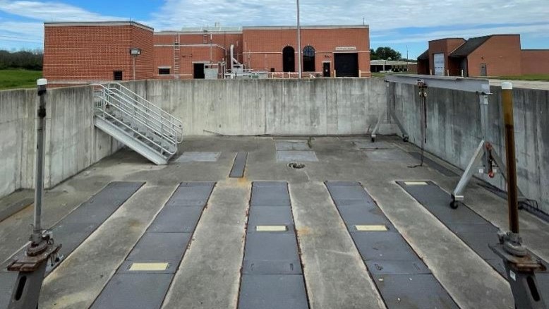
Here’s the first part of the route that the 37.3 million gallons of wastewater coming into the plant each day travels: wastewater enters Headworks, where it goes through screening processes. Next, it flows into the grit removal basins and then on into the main flow splitter structure. (Note: the plant has multiple flow splitters, but in the interest of word count, all mentions of “flow splitter” in this article refer to the main flow splitter.)
Because the Nine Springs plant has an east and west treatment route, the wastewater is then divided inside the flow splitter between the east plant and the west plant. Stop gates inside the structure allow operators to control the quantity of water that goes to each side of the plant. Operations manager Alan Grooms says they want the volume going to each side to be relatively equal, so adjustments aren’t done frequently. But when they’re needed, the ability to make those adjustments is essential.
A critical hydraulic control structure
Why is the flow splitter so crucial? “So I can sleep at night,” jokes Alan. But being able to control the flow between the east and west plants is essential for process control and infrastructure maintenance – especially when the work requires flow modification or even a shutdown. It can also be crucial in high-flow events.
And sometimes there are plant performance issues that require flow adjustments. Since we use biological treatment for cleaning wastewater, the health of the treatment system depends on the work of our microorganisms. “We want to make sure the plants are working relatively equal to what they’re capable of and how healthy they are,” says Alan.
How the health of each plant would be maintained during the flow splitter rehabilitation was a crucial question when planning and designing the project. One of the questions asked of Alan during planning was how long can we stop the flow to one side of the plant?
“My response was, how long would you not feed your dog?” says Alan. The microorganisms in the treatment process rely on the organic matter in wastewater for food, so you can only restrict flow for a limited time before the biota is disturbed and treatment degrades.
Vulnerable to corrosion
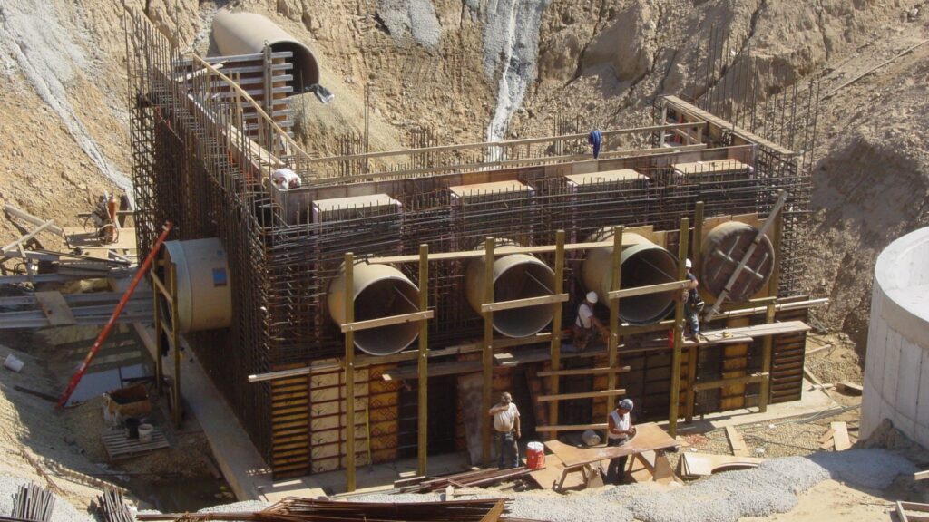
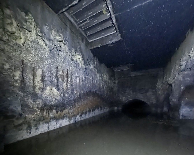
The Nine Springs’ flow splitter was constructed in 2004-2005. Its concrete and metal components have deteriorated significantly over the years, likely due to the high levels of hydrogen sulfide in the wastewater. “The day of travel through our long force mains means more time for corrosive gases to form,” says Alan.
Once the wastewater reaches the flow splitter, the turbulence created by it flowing over weirs and being split between the two plant sides causes the built-up gases to release. The gases then combine with the moisture to form acid, which eats away at the concrete and metal.
Inspections of the flow splitter are challenging and thus rare. But in 2020, deteriorated gates inside the structure were discovered, prompting a detailed video inspection in 2021. This revealed areas where the concrete walls had significantly deteriorated and elevated the concern for the integrity of the structure.
Rehabilitation and design improvements
As the project engineer for the Flow Splitter Improvements project, Kailyn Hackeloer-King and the engineering team had the challenge of prioritizing the necessary rehabilitation work while incorporating new design elements to make improvements to the structure – particularly its inherent vulnerability to corrosion.
“Addressing how the gases within the structure would be ventilated was a priority because we believe that is the root cause of a lot of the damage,” says Kailyn. The underground flow splitter originally had a concrete top over it and a ventilation system prone to failure. “We didn’t feel it would be appropriate to just leave that in place, so we decided to move forward with passive ventilation,” says Kailyn.
Most of the structure will now have an aluminum grating top to allow the gases to escape. Another design improvement aimed at reducing corrosion potential will be replacing some concrete and metal parts inside the structure, such as weirs, troughs and stop plates, with reinforced fiberglass parts.
A long-term construction gain: the bypass channel
One of the biggest improvements to the flow splitter structure is the installation of a permanent gravity bypass channel. Emptying the structure by bypassing flow around it is necessary for the project’s rehabilitation work. This could be done either by pumping or installing a bypass channel. Kailyn says that selecting the bypass option was less expensive than pumping, and it provided an opportunity for redundancy by making the bypass a permanent structure.
“We’re setting ourselves up so it will be faster, easier and cheaper, in the future to do inspection or rehabilitation work,” says Alan.
The new grated covers will also help with inspecting the structure. “Having the grating alone will allow you to see into the structure even without doing a full shutdown,” says Kailyn.
Early project progress and timeline goals
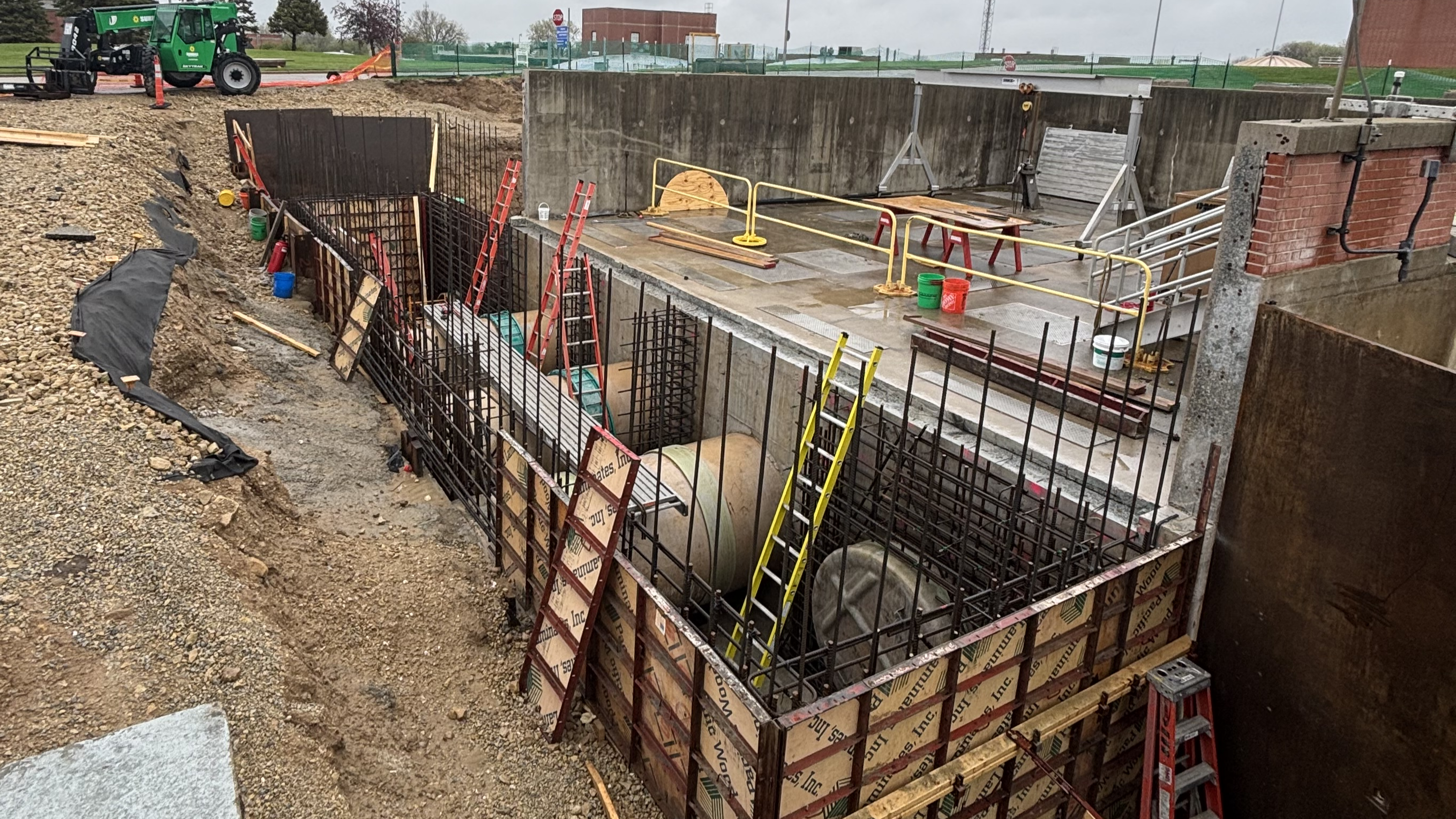
At the end of April, the structures for the bypass channel were being formed with rebar and concrete. At over 26 feet deep, this work was done in vertical stages of pouring and curing the concrete.
Kailyn says the goal is to start bypass pumping the first week of July; the pumping will last about two weeks while the gravity bypass channel is completed. For Kailyn, this will be an exciting and maybe sleepless phase. After the bypass channel is complete, it will be used until late September while the rehabilitation work inside the flow splitter is done.
“I’m excited to see how it ends up functioning because it’s a key component in our construction sequence,” she says.
By Jessica Spiegel
For more articles on project spotlights and the work of our teams, visit the District category of our blog.
